Taking "Cantor" beamshots
I use ceiling instead of wall as a screen.
Below marked with yellow are parameters that
must be measured/recorded by you during the shooting.
Preparations
Camera must have raw output
(and apparently, also manual exposure mode).
You must know what raw means, how to process it, etc.
Find a room. Ceiling — plaster (matte), uniform. Distance (height) from
headlight to the ceiling (lC + d_3 on the schematics below)
— the larger the better. Let's say ratio of the
headlight aperture (size of the hole from which light goes out) over
this distance should be around 0.01-0.05, the smaller the better (makes
headlight point-like). The room
must be dark (not externally lit — compared with the headlight).
Room's walls ideally should be either
black, or far away (mine are not). Ceiling area should be big enough so
that the beam pattern fits into it.
The camera must be aimed straight up vertically, i.e., perpendicular to the
ceiling.
If using a quality camera (ones with detachable lens probably have lens
optical axis very much
perpendicular to the sensor, and intersecting it very close to its center),
there's a simple way to achieve this: hang a small weight from a ceiling lamp,
almost down to the floor. Put the camera right beneath the weight.
Remove the weight. Orient the camera such that the hanging point on the lamp
is at the image center.
If using a cheap compact, orient it so that it looks good.
Record the distance (height) from camera to the ceiling,
lC (all lengths in cm).
Camera lens should be zoomed-out enough (= wide-angled = focal distance small)
so that (with the above conditions) it captures the interesting part of the
pattern.
Make a comfortable "cradle" for the camera —
so that you can reliably make several shots with identical
geometrical settings. How I did:


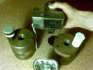
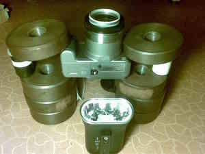
The dumbbell weights as a "cradle" basement — to allow me to see the camera screen
from underneath (yes, very awkward, but OK to discern the needed settings).
I put some (rubber) pads to put the camera horizontally
(and to not scratch the screen) — first photo.
Then I pressed the camera down with two other dumbbell weights — second photo.
Now when I push camera buttons carefully,
the camera won't move, at all.
Even better — if the camera supports remote control from a nearby PC.
Owners of (most of older) Canon compacts are blessed with
CHDK, an open-source firmware
extension that allows RAW, manual shooting settings and remote control using
chdkptp.
The above dumbell basement setup can then be simplified to something lighter.
Headlight orientation.
The headlight hotspot may lie off vertical and/or horizontal axis
(i.e., non-zero pitch and yaw).
On figure below pattern is symmetric wrt vertical axis (i.e. pitch non-zero,
yaw zero) because that's what we most often would want.
The pattern should not be rotated (roll should be zero; if it's rotated,
it will just take more efforts to correct later).
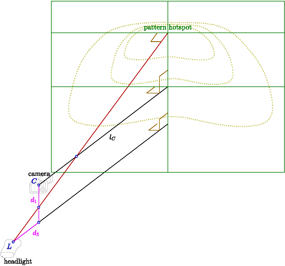
Positioned however the headlight must be right "below" the camera:

(image created in carmetal
and inkscape)
Measure distances from camera to light d1,d3.
As shown, both d1,d3>0.
If the light is positioned differently wrt camera, one or both of
d1, d3 may be negative.
Once happy with geometry (make test shots), record all the settings (for
yourself): the horizontal (on the floor) camera/headlight position,
and how you set up the "cradle" (whatever): in case
you'll need to re-shoot, it'll be easy to re-create the cradle.
Put a ruler on the ceiling (e.g., by pressing it with some long pole),
around optical axis of the camera.
Make a shot of the ceiling (with your final geometry settings),
remove the ruler, convert raw to jpeg (applying all usual distortion
corrections), open it in an image editor and find the corresponding length
of the ruler in pixels (in Gimp — "Measure tool"), say 393 px for 33.3cm.
It is important to use raw here because built-in camera software may
cheat something with resolution (mine does).
The ratio of lengths (cm/pixels) is scale_cm_px, in this case
33.3/393. (remove the ruler)
If later you change zoom (=field of view, FOV), it will change this
scale_cm_px ratio, so need to re-measure it again.
The 4 above parameters, lC, d1,d3, scale_cm_px
is all what's needed from geometrical setup.
Few more numbers are needed for camera exposure data, and calibration.
Camera settings
Reminder: exposure value (EV) of a shot is: exposure_time *
ISO_setting / (aperture_number)^2
(times a const, which is irrelevant for our purposes).
Skippable exposure primer in brown.
Related to optics (a bit physics), and is a big topic in itself.. So
very briefly. Exposure is determined by a triple of parameters:
sensitivity, aperture, shutter. To get some exposure value (1 number), if
given two parameters (2 numbers), you have a freedom in choosing 1 of them.
There are actually 3 parameters, so there are two freedoms. Each freedom is a
trade-off. It is these freedoms/trade-offs that make the photography a
rich creative subject. And makes it difficult for me to guide you.
Sensitivity is a control of internal amplifier. Minimum turns the
amplifier off. Higher settings let you see the darks under very dim
light, but add more noise. A trade-off #1. I set to min (ISO100; the amp is
minimal, "off") only for piece of mind — fewer things to care about. Although,
since the image will be smoothed anyway, amp's noise really shouldn't matter.
Aperture is the size of the lens hole. Determines depth of field = DOF =
the range of distance that appears acceptably sharp. The smaller
aperture (=closed, numbers high, like F/16) — both near objects, and far
objects will be in focus, sharp. Good for beamshots, bad for portraits.
The larger (=opened, numbers small, like F/2.8) — only some objects will
be sharp in focus, background will be blurred. Bad for beamshots, good
for portraits. A trade-off #2. (also there's a complication: the more it
is open — the more optical artifacts and distortions/aberrations).
Set it to max open (to not wait long times), then close it to get
the whole pattern in focus (and to reduce aberrations).
Shutter. No trade-off. (Moving objects may be blurred for long shutter time,
but that's not related to beamshots that are static).
For example, to get
everything focused if it's a little out of — close aperture. Or if you
are tired to wait minutes, increase sensitivity to make it faster, or
try opening aperture — and check that everything is still in focus.
Note also that aperture=F/2.8 and sensitivity ISO=100 on a cheaper
compact camera may give depth of field and noise roughly the same as
aperture=F/16 and sensitivity ISO=3100 on a full-frame DSLR.
Not going into it.. I'll just mention
the keyword: "crop factor", in this case it was 5.6.
Focus method — depends on camera. I guess better use automatic. On my
camera I chose manual mode, but pre-set it using auto. So I verified
only on one shot that it's in focus, and all other shots will then also
be in focus.
Experiment a bit.. obvious goals — ceiling focused (actually a bit
unfocused is also OK), pixels values high,
but not over-exposed. The camera may have some over-exposure helpers,
but the definite way to check this is in a raw converter (in ufraw —
zoom 1:1, pan to brightest area and press the appropriate button
at the bottom)
Use self-timer on the camera (1-2s) — to not shake it while
pressing the "Shoot!" button.
White balance is irrelevant, use any.
(the internal camera flash light must of course be disabled)
Beam shooting
Charge the headlight batteries, to have stability in beam intensity (just in
case). Decide on the brightness mode you'll shoot. Brighter better, but
batteries will drain faster. Record the brightness mode
for later repeat-ability. Ideally
measure the consumed current and voltage
(interesting is both LED and the driver board) to get power.
The output zM can then be divided by this power to get
per 1W LID (I like this normalization: what illumination we get
with a given 1W of power).
You really need to make at least
two beamshots with different exposures. For a high-contrast cutoff headlight
(Saferide) I found I needed three beamshots, separated by 3 EV stops
(8=2^3 times of exposure value).
The first beamshot captured brights, the second beamshot — middles
(with brights over-exposed), third — lows (brights and middles over-exposed).
With bigger-sensor SLRs it may be enough to use 2 instead of 3 shots.
The n-th (n>=2) element of rEVs array, rEVs(n), is the ratio of exposure
value of n-th beamshot over EV of the (n-1)-th one.
For example, assuming same aperture and sensitivity between all shots,
if 1st beamshot used 1/8s, and 2nd 1s, then rEVs(2)=1/(1/8)=8.
If there are M beam shots (normally 3), there will be M-1 such ratios here,
and they need to be passed as rEVs(2), rEVs(3),...,rEVs(M).
Calibration
Take any light source, having a uniform illumination in a small angular patch
(to avoid light scattering from walls), put it where headlight was during
beam shooting, and direct it straight up to the ceiling
(on the shooting geometry figure — to point O_1).
Measure illuminance there with a luxmeter (they are cheaply available,
unlike luminance meters that are expensive), call it E0
(it won't be passed to get_LID directly, but needs to be recorded,
so marked in yellow), for example 3136 lux.
Remove the meter and make a shot of that same place (O_1),
with the camera where it was during beam shooting.
Let pixel value be (after raw converter, no gamma-encoding)
VC, for example 138.
Let rhc be the ratio of exposure values (EV) of headlight highs
shot (the first one from beam shooting) and of the above calibration shot. For example,
if only exposure time was increased, from 1/60s for calibration shot,
to 1/30s for headlight highs shot, and the aperture and ISO were not changed,
then rhc=(1/30)/(1/60)=2.
The 3 above quantities should be combined as rhc*VC/E0 and
passed as the first element of rEVs array, that is, in rEVs(1).
For the above numbers, it's 2*138/3136.
If you skip calibration, set rEVs(1) to 1 (any other value is also fine).
You'll loose absolute values, but still have relative (essentially normalized)
LID.
For details, in addition to the get_LID() source, see also 2nd section of
Formulas pdf.
This array, rEVs, is the last set of numbers that are needed to be
measured/recorded during the shooting.
Panoramic shooting
Everything remains same as above (except the light will have to
shine offside = not as shown on schematic above).
Be sure to block unwanted light: after getting to the walls it will reflect
to the ceiling and distort the pattern.
If you re-position the light, or camera, record the new distances.
There's no need for re-calibration.
Part 2, processing data
If Raw/Matlab/Octave looks daunting, I may be able to help you at this point.
In addition to the raws, I will need the yellow-marked parameters from above.
DO NOT READ THE BELOW:
script, and the workflow will be heavily re-structured,
to allow panoramic beam image.
Below marked with light green
are parameters containing your processed data, to pass to get_LID().
Make sure the converter settings are sane, e.g., it doesn't adjust exposure
after your previous GUI session (I delete config files).
Human's eye is more sensitive to some wavelengths than to others,
so the photos should be grayscaled appropriately.
Not sure, but the correct way seems to be getting the
luminance from CIE Lab space, after profiling the camera.
I didn't profile, and just used ``luminance'' option, whatever it meant.
There's always some angular discoloration, I ignored it.
Apply corrections, whatever available. Distortions are
particularly important on cheap cameras; don't know about detachable lens.
Especially on cheap cameras, it may make sense to profile corrections
(e.g., lensfun's author instructions) yourself,
because there may be large camera-to-camera variations.
Gamma encoding must be off, i.e., gamma=1, i.e., image must be linear.
There should be no need for rotation. The larger the need, the more
unaccounted errors we neglect. So, rotate for better aesthetic appeal,
or re-shoot so that it looks straighter.
I found batch processing (after manual inspection) is great — all your
actions are easily repeatable.
The jpeg file names need to be passed to get_LID() as cell array in the
fns parameter, brightest first.
Open well-over-exposed jpeg (converted) image in an editor, and determine
the usable area of the ceiling (in Gimp — rectangle select tool):
crop_2,crop_1,crop_sz2,crop_sz1.
First pair=coordinates of upper left corner, second pair=size,
2=horizontal, 1=vertical. Make size multiple of 10.
NF — just pass [120 30]
in most cases.
It defines how much smoothing will be done.
Larger #s will make more detailed (and noisy) image, smaller — smoother.
Two numbers — for the two dimensions of the image.
Finally
With all the necessary input gathered, put all
script sources somewhere, together with jpeg images.
The order of the input parameters:
[alsM,besM,zM] = get_LID(fns, NF, crop_2,crop_1,
crop_sz2,crop_sz1,
rEVs, lC, d1,d3, scale_cm_px)
Run (in Matlab/Octave; example, put your own numbers):
[alsM,besM,zM]=get_LID(
{'sr80_m1.jpg.jpg','sr80_m2.jpg','sr80_m3.jpg'}, [120 30], ...
420,720,3040,1860, [2*138/3136 30/4 8], 265-20, 10,10, 33.3/393);
If all is well, visualize:
main_vis(alsM,besM,zM/3.5448, 2.4, 'SR80');
(intensity divided by 3.5448 — to give per-1W normalization)
The first three parameters are from get_LID() output, 4th is tilt angle
(not needed for wall visualization), and 5th is title string.
What to visualize (wall, 3D, road, etc) — is determined by vis_* flags
(=0 or 1) at the very beginning of main_vis().
You can manually change limits of displayed region in appropriate places with:
xlim([-20 20]); ylim([-8 17]); (this is for wall vis).
It's also easy to get camera zoom for better far view
(the camera_tilt and vis_zoom variables).
If you want to just try the scripts without shooting and raw-processing,
there are 3 example jpgs in jpgs_for_sim directory.
(and the rest of jpgs_for_sim/*.jpg files are in big-files archive).
Consider thinking about physics and studying the code — to double-check me.
Main part is the get_LID() function, it's short really.
And despite the length of this page — it's all not difficult really.


